10W Bluetooth Guitar Amp - Part 2 - Better Sound
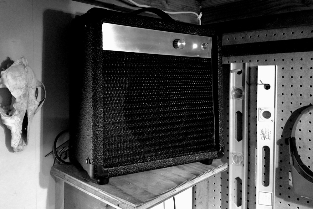
Last time, in Part 1, we retrofitted an old guitar amplifier cabinet with a 10W bluetooth-enabled mono amplifier, based on the LM1875. The results have been nice, but the audio quality is noticeably lacking. The sound has a dull/muffled quality, and there is hardly any punch or body to the bass.
Here in part 2, to help improve the sonic experience a bit, I evaluate different speaker drivers, build a simple passive crossover circuit, and improve the acoustic properties of the guitar amplifier enclosure.
Things to Fix
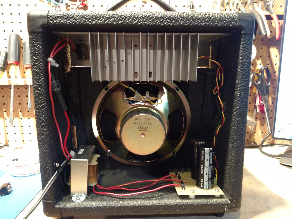
The first issue, the dull muffled sound quality, is due to the speaker driver: the original Peavey 4Ω woofer that came with the amplifier. Woofers typically have a range of around 60Hz up to as high as 5kHz. Now I doubt that the original Peavey driver had a range nearly that wide, but probably still in the neighborhood of 100Hz-3,000Hz. Commonly, the human ear can hear between 20Hz to 20,000Hz. So, that leaves out a sizable chunk of the audible spectrum! Most of the mid/vocal range, and all of high range are left entirely out of the party.
The second issue, is that there’s really not much body or punch to the bass. Even though the driver is a woofer, not a lot happens with the sound waves it does manage to generate. This has to do with the enclosure. Open back guitar amplifier cabinets are designed to accentuate the mid and high range, and to throw sound broadly around a room. It also can help musicians hear each other on stage, in the absence of dedicated monitor speakers. The downside is that the low end frequencies end up feeling rather lifeless.
Part 1 of building the amplifier was a blast, and I learned a ton. So, let’s iterate and give this amp some punch!
Speaker Driver
The first thing to do is to find a speaker driver that is capable of covering a wider range of the audible spectrum. Normal speaker systems account for this by having multiple speaker drivers. Sometimes having two, three, or even more individual speakers built into the cabinet (you often see this as “two-way”, “three-way”, etc). The speakers are wired in such a way so that each covers a particular band of the audible spectrum. Woofers can cover the low and part of the mid range, and tweeters can cover the rest. In my case, the guitar amplifier’s enclosure is pretty small, so to cram multiple speaker drivers into it would ultimately require sacrificing the diameter of each speaker driver. A speaker’s ability to produce sound is proportional to its ability to move a volume of air (“Volume displacement”, or Vd). Volume displacement requires a large cone, and maximal inward and outward displacement (called, “cone excursion”), which can be achieved in two ways. Either have a really large cone, with marginal cone excursion, or a smaller cone, but with greater cone excursion. Generally, it is more practical, and less expensive to construct drivers that have a large cone, which consequently require lesser cone excursion. This is why you typically see woofers with large diameters, rather than small, very powerful ones.
A good option for the guitar amp enclosure, which can fit an 8” speaker driver, might be what are called “Full Range” speakers. These typically have more than one cone built into a single chassis, where each cone is responsible for a particular frequency range. They tend to be more expensive than individual drivers, but can be integrated into more space constrained enclosures. You can find full range speakers in a wide variety of sizes, and prices (from $5 - $300, or more).
Here’s one that might work. It’s by Speco, and designed for in-ceiling home audio installations. It’s a little on the small side, but seems like it could do the trick.
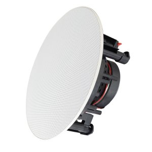
- 1/2” Tweeter
- 6.5” Woofer
- 8Ω
- 65W
- 48Hz - 21kHz
- Built-in crossover circuit
I was able to find one of these at a local speaker repair shop, for $20. After removing the mesh and mounting bracket, installation was simple (on account of the built-in crossover circuit. More on that later). While it sounded much better than the old driver, and it is certainly good enough, curiosity got the best of me. I want to see what I can get out of this little amp, and giving it the right driver could make a world of difference. Moving on up the price range…
Now, this one seems like it’d have some teeth! It’s made by Celestion, and is marketed as a “Professional Full-Range Driver”. Whoa!
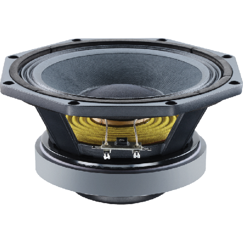
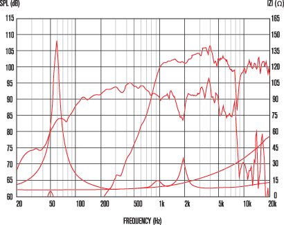
- 1.4” Tweeter
- 8” Woofer
- 8Ω
- 200W
- 70Hz - 20kHz
- No built-in crossover circuit
The novel thing about the FTX0820 is the way they designed the motor driver. It’s common for full range speaker drivers to have two independent motors that drive the woofer and tweeter. The FTX0802, on the other hand uses one, very large magnet to drive them both. The result is that the tweeter sits inside of the woofer, and the sound waves that they emit have a center point that very near each other, apparently making a composed sound that is more coherent. I wonder if I can sense the difference… I’m betting on this one strictly because of its weight–almost 10 lbs! Punch!
The one disadvantage of this driver is that it does not have a built in crossover. What does that mean?
Speaker Crossover
A crossover circuit is responsible for splitting an audio signal into two or more frequency ranges. Since a tweeter and a woofer both like to operate at different frequency ranges, we need to be sure and feed the correct frequency band to them, to eliminate distortion. Speaker cabinets typically contain what’s called a passive crossover that is specifically tuned to the speaker drivers it contains. In a crossover circuit, you define a specific frequency, at which point, anything under that frequency gets routed (or crosses over) to one path, and anything above it gets routed to another. A passive crossover does not actively re-amplify the signal, resulting in some amount of signal loss. Active crossovers incorporate amplification, and even sophisticated DSP analysis to precisely tune the crossover frequency response curve. Active crossovers are typically only found in professional or high end audio installations, and occupy a separate rack mounted device. For passive crossovers anyway, like practically everything involved in DIY audio electrical engineering, there are many ways to design and build such a circuit. So many that I don’t that I can fully appreciate the breadth of public opinion about the merits of each one. So, let’s pick a simple design, and see what happens.
The FTX0820 has one woofer and one tweeter, so it will require a two-way crossover to split the audio signal into the appropriate low-range and high range frequencies for each. The FTX0820 came with a handy, though cryptic app note “[recommending a] crossover of 2,200 Hz/12 dB slope”. Uh?
The 2,200Hz refers to the crossover frequency. E.g. anything under 2,200Hz will be sent to the woofer, and anything above it will be sent to the tweeter. The 12db slope, though? So, a crossover circuit isn’t exactly like a two-way valve allowing frequency ranges to go in strictly one way or another. By design and necessity, built into a crossover circuit is a frequency v.s gain response curve, allowing the frequency ranges defined by the crossover to slightly overlap. The 12dB refers to the signal decay per octave above or below the crossover frequency. You typically find crossover circuits in 4 slope varieties. The terminology for them is thus: A 6dB/octave slope is known as a First Order crossover, a 12dB/octave slope is known as a Second Order crossover, and so on. To achieve a particular slope (or order), requires varying degress of design complexity. A Second Order (or 12dB/octave) crossover, thank the heavens, is pretty straight forward.
Jumping to the chase, here is the circuit diagram, and component values for a 2-way, 12dB/octave Butterworth crossover, with a crossover frequency of 2,200Hz, tuned to drive an 8Ω tweeter and 8Ω woofer.
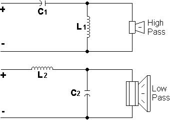
Values
- C1, C2 - 6.3μF
- L1, L2 - 0.8mH
The values chosen were derived using the Butterworth crossover formula. There are other formulas which you can use to determine the appropriate component values, and each have slightly different characteristics. See Audio Crossover 2, for more details about the tradeoffs between them. The Butterworth crossover is nice because it produces decent results, while minimizing the cost of the inductors (which can get spendy and huge). It also has a friendly name.
The calculations were carried out by this handy-dandy calculator at esraudio.
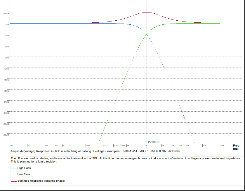
Here is the frequency response curve of this particular crossover. Notice that when considering the combined amplitude of the low and high end curves, near the crossover frequency, there is actually increase in amplitude. That’s not necessarily a good thing, but it’s a byproduct of the Butterworth crossover design.
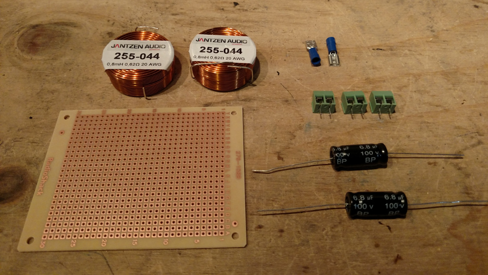
Parts
- 2x - 6.8μF 100V bi-polar capacitors Parts Express
- 2x - 0.8mH 20AWG audio inductors (Air core, or solid core) Parts Express
- 1x - Veriboard
- 3x - 2 pole 5mm pitch screw down terminal blocks
- 2-4x - 0.205” female crimping speaker connectors
Layout & Assembly
Since this is such a simple circuit, the layout should be straight forward. To help minimize stress on the solder joints, I lay the inductors on their sides, and affix them in place with hot glue.
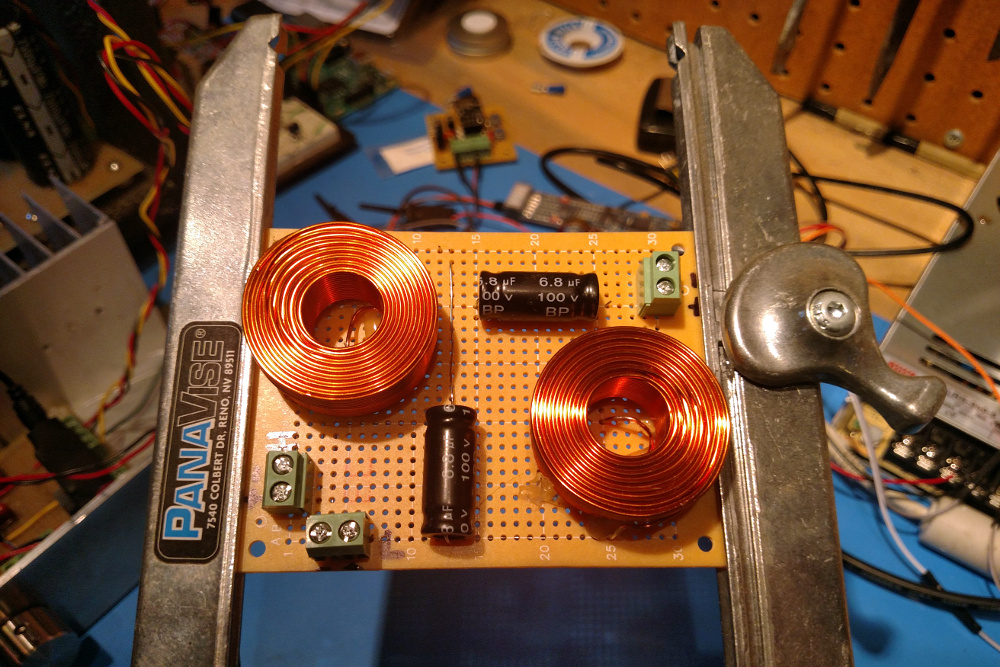
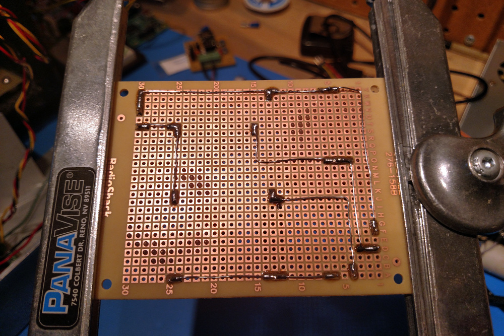
And that’s really all there is to it. I made sure to mark the + and - signal paths. For best results, the hi-pass path should be connected inversely to the low-pass path. Due to the nature of the design, the hi and low signals arrive 180° out of phase, so hooking up the two speaker driver components inversely to one another aligns their phases. This isn’t strictly necessary, but is apparently nice to do, especially since the acoustic centers of the tweeter and woofer are aligned within the FTX0820. Again, I’m not sure if I would know the difference.
Cabinet
The second order of business is to see what can be done about the cabinet. It has an open back, and I suspect that this has much to do with the flimsy bass response. Resonance is often employed to enhance the bass frequencies produced by a speaker driver. It’s the reason you typically see sealed cabinets with port holes cut into them. That structure allows the bass frequencies to resonate within the cabinet, and then to exit in a controlled way, either towards or away from the listener. This design is called a “bass reflex”. The sealed cabinet allows certain frequencies to resonate, making them more pronounced and richer. At a certain frequency the enclosure no longer resonates, the port holes then (when done correctly), continue the resonant effect, thereby extending the overall frequency response of the cabinet.
The diameter and length of each port hole is important, and depends on a couple of factors. 1) The volume of the cabinet, and 2) to some degree, the diameter of the speaker driver. I’ve read that, for an 8” driver, a total port vent diameter of 4” is recommended. That certainly won’t fit in this enclosure, but we can try to get as close as we can. An alternative is to have two port holes. Our goal is to get close to 4”. The maximum hole diameter that the enclosure’s front section can support is around 2” on either side of the speaker driver, so if we place two 2” holes, that would give us \(d_{t} = \sqrt{d_{1}^2 + d_{2}^2} = \sqrt{2^2 + 2^2} = 2.82\). Not exactly the 4” equivalent we’re looking for, but it’ll do. Now, the length of each port needs to be proportional to its diameter. The guide I found suggested that a reasonable length for a 2” port is around 2.3”. Great, so two 2” diameter ports, each 2.3” long. No problem.
Since we’ll be making a new front panel to hold the speaker driver and port holes, let’s make it look nice, by covering it with speaker grill fabric.
Materials
- 1/2” plywood (roughly 10” x 10”)
- 1/4” plywood (roughly 12 3/4” x 12 x 3/4”)
- 1/2” - 3/4” thick scrap (roughly 8” long)
- 2” PVC pipe (roughly 6” long)
- 2-part epoxy (JB-weld works great)
- 1 yard black speaker grill fabric Parts Express
- Black satin spray paint
- 12x - Drywall screws
- 1/2” silicone or foam weather stripping with adhesive backing
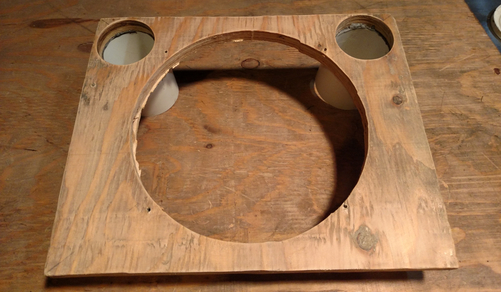
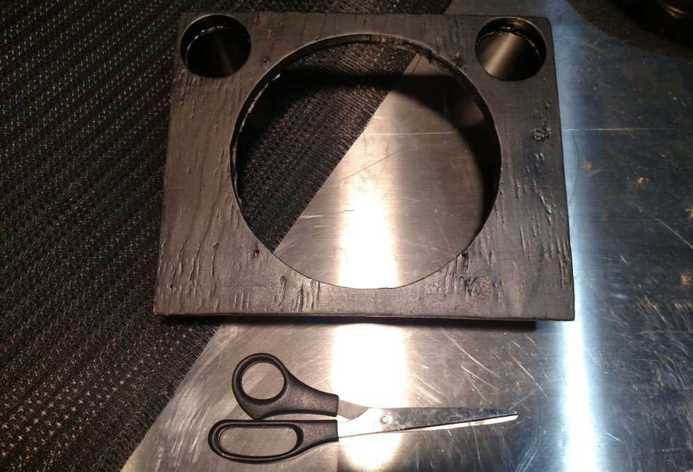
The first step for this cabinet is to cut out a 10 3/4” x 8 3/4” piece of 1/2” plywood. Cut out a 7.36” center hole for the speaker using a jig saw, a router, or using a Dremel with a hole jig. Then, using a 2” hole saw, drill out two holes adjacent to either side of the center speaker cut out. Be sure to leave space between the center hole, and the port holes to allow for the outside diameter of the speaker driver, and the outside diameter of the PVC piping.
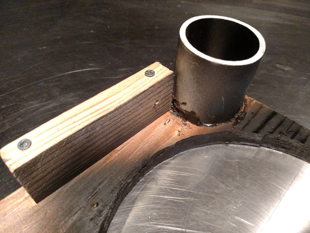
Next, cut two sections of PVC pipe to length–2.3” long. Then, using the 2-part epoxy, glue the PVC pipe sections to one side of the plywood, and let cure.
To allow the front panel to be fastened to the sides of the cabinet, take some scrap 1/2-3/4” lumber and attach it to the sides of the front panel, and paint it black!
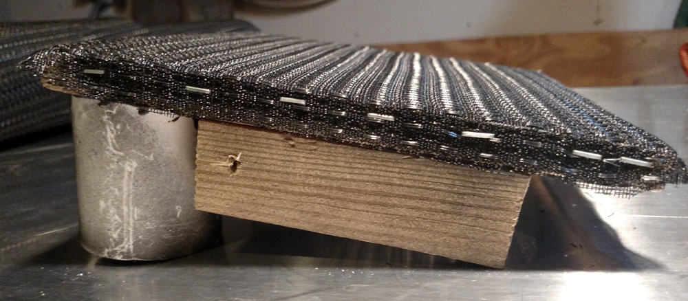
Now it’s time to do some upholstering. Cover the front of the panel with the grill cloth.
Stretch, and fasten the grill cloth using a staple gun. As you go, make sure to keep the pattern even and level along both axis of the panel. Not so easy…
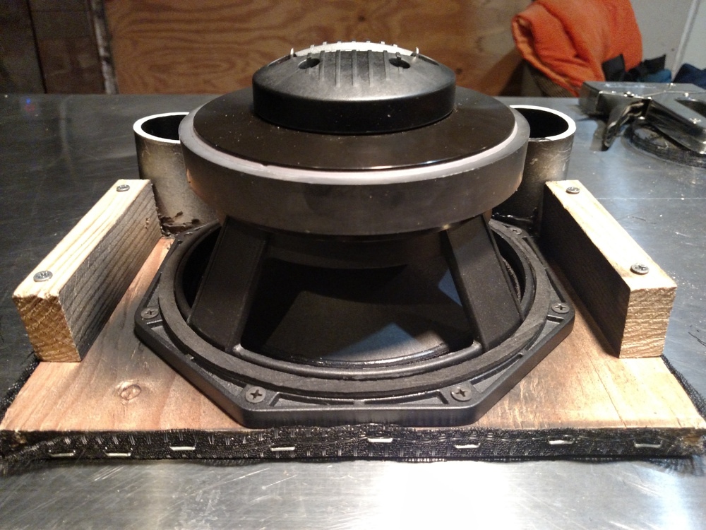
Now, just try it on for size. A perfect fit, without any room to spare.
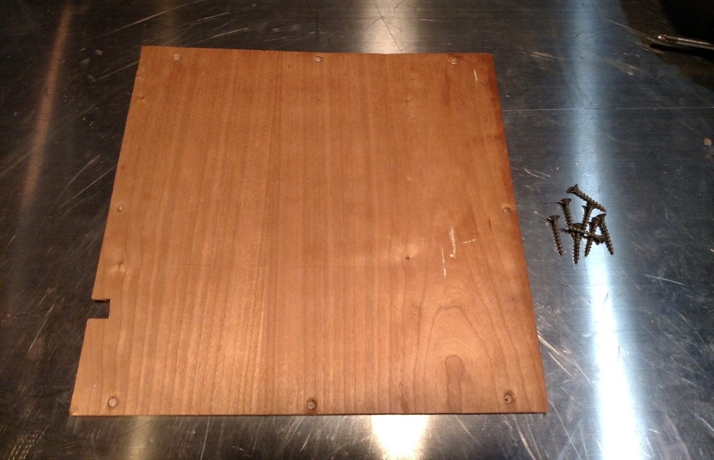
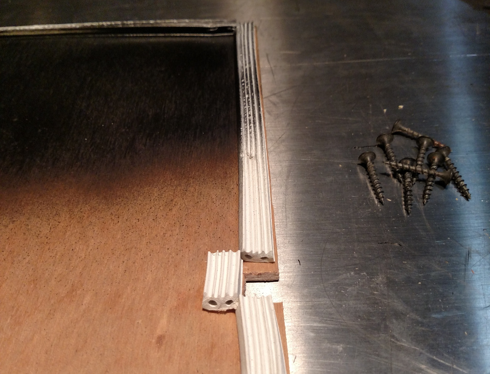
Seal it up! For the back panel, I chose some 1/4” plywood, cut to 12 3/4” x 12 3/4”, cutting out a notch for the power cable.
To seal everything up, use 1/2” silicone or foam weather stripping with an adhesive back. Applying this to the inside of the back panel makes for a great seal to keep those resonating sound waves nice and happy. Also, paint the interior black so that it will not be noticeable from the vent ports, as well as the back side to give a clean look.
All Together
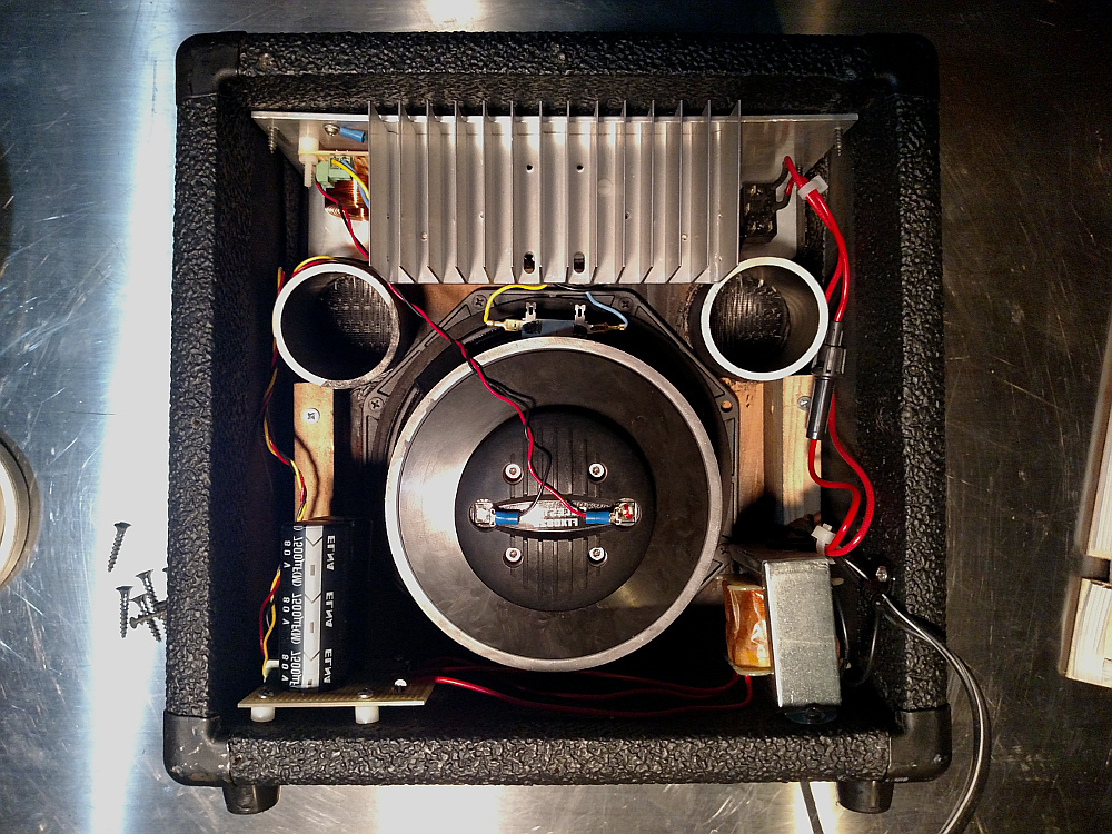
Putting everything together is straight forward too. The addition of the grill fabric seals the gaps between the front panel and the sides of the cabinet, and everything else fits nice and snug inside. If you’re wondering where I stuck the crossover, I attached it to the aluminum chassis, next to the amplifier. You can see it poking out at the top right. Same as with the amplifier, the circuit board is fastened to the chassis with nylon screws and 1/4” spacers.
The new speaker driver is huge. Everything JUST barely fits!
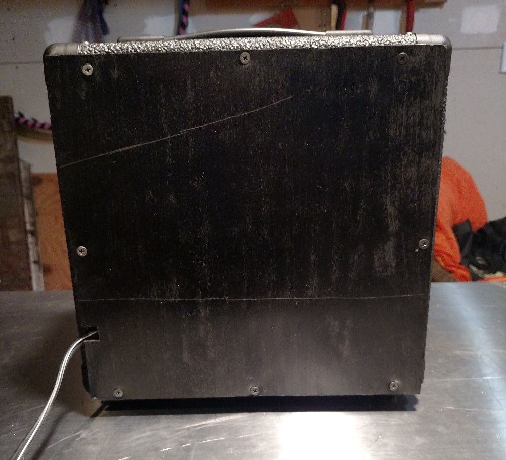
Button up the back, and we’re ready to dance!
I now have a lot of appreciation for speakers and those who design and build them. The minutia involved with designing good sound equipment is extraordinary. I cut some corners here and there, but in general, this design covered a ton of fascinating details. And the results?
Results
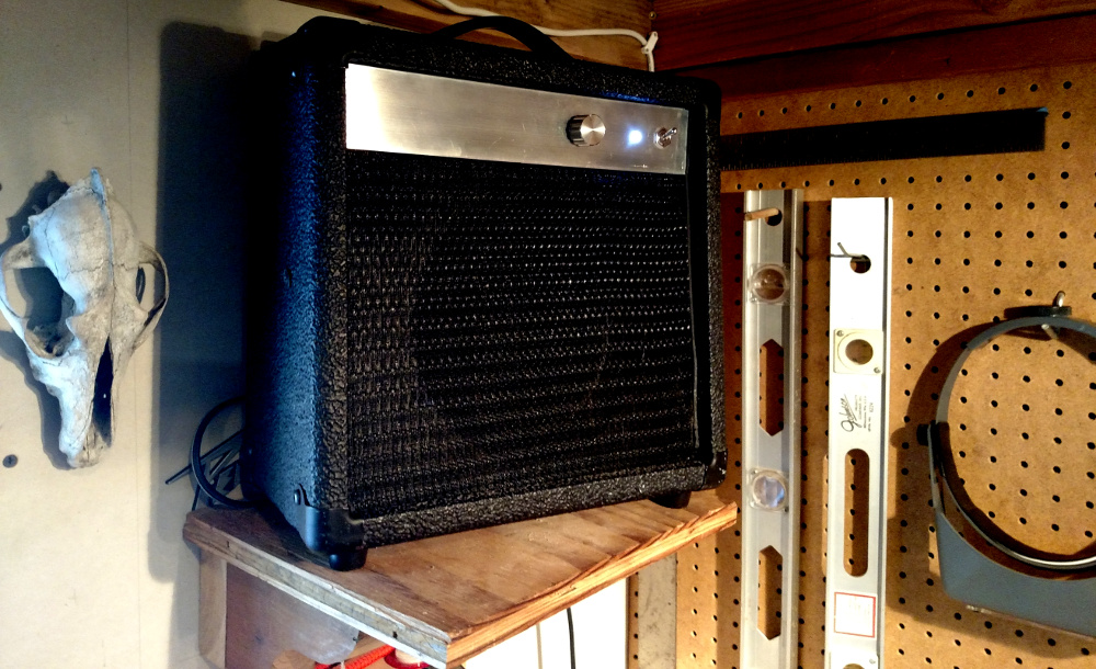
Yes! This sounds amazing! These two additions made a world of difference. The sound across the range is extremely vibrant. The low-end punch that I was hoping is spot on, and I am enjoying the clean logo-free look as well.
The one thing I can say, is that introducing a true full range speaker, I can hear just how crummy compressed audio really is. It’s easy to hear the artifacts and warble. I’ve also noticed that the FTX0820 has a particularly pronounced and powerful high frequency end. It’s almost to the point of being irritating and jarring. Since I did not include any kind of mid/treble tone control on the amplifier, I’ve found that using a software EQ to roll off some of the high end, to be really helpful. Had I included tone control, to account to the wide variety of source audio content that we have at our fingertips, software EQ would be unnecessary.
Anyway, another great build with lots of interesting facets, and with a really stellar result!
References
- Why Nominal Diameter Tells You Nothing About Tone - http://barefacedbass.com/technical-information/speaker-size-frequency-response.htm
- Audio Crossover - https://en.wikipedia.org/wiki/Audio_crossover
- Bass Reflex Speaker Design - Easy Explanation - http://audiojudgement.com/bass-reflex-speaker-design/
Comments