10 Watt Bluetooth Guitar Amp - Part 1 - Retrofit
It’s been pretty quiet in the lab this summer, and playing around with an audio project has always seemed like a lot of fun, though, until now I’ve been a little too intimidated to try it out. My AM/FM radio gave up the ghost a while ago, so perfect, I thought. Now would be a great time to shake things up and modernize the lab with a custom bluetoothy speaker system on the cheap.
Some design goals:
- A self-contained amplifier/speaker system, that’d be easy to hack.
- Something stylish to snazz up the lab.
- Use an off the shelf bluetooth adapter that’d be easy to integrate into enclosure and the amplifier, and one that’s easy to supply power to.
- Something in the 10-20 watt range.
Trial and Error
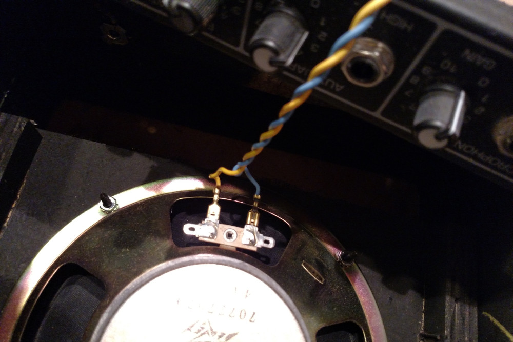
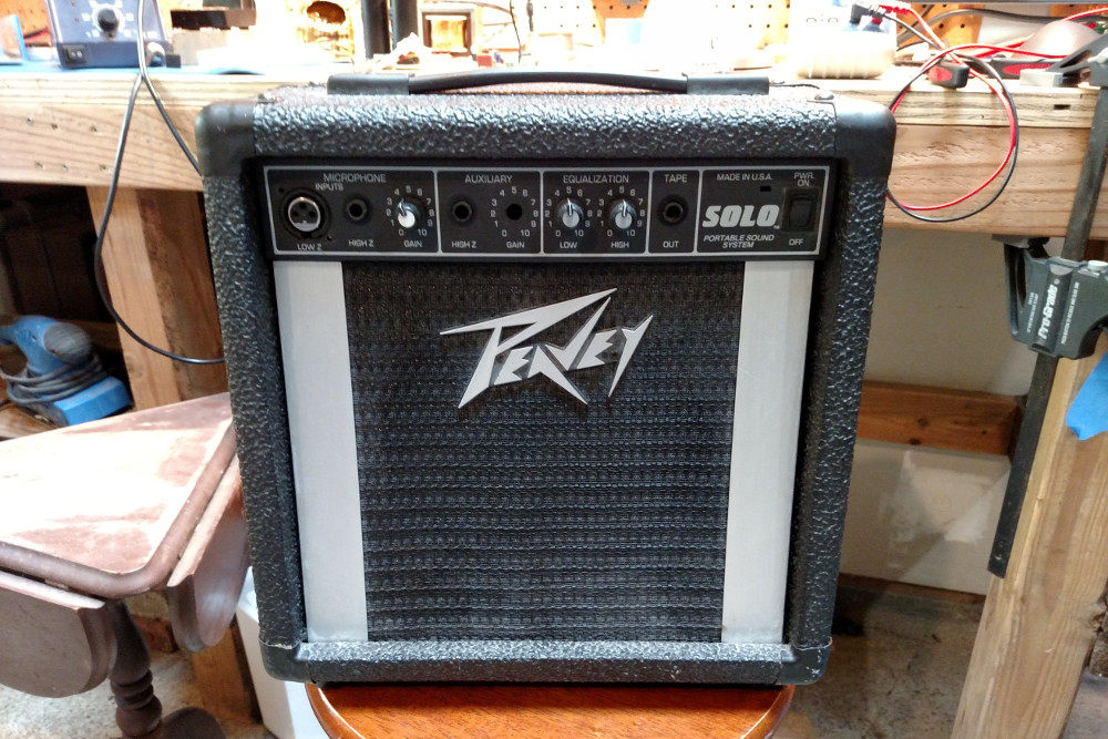
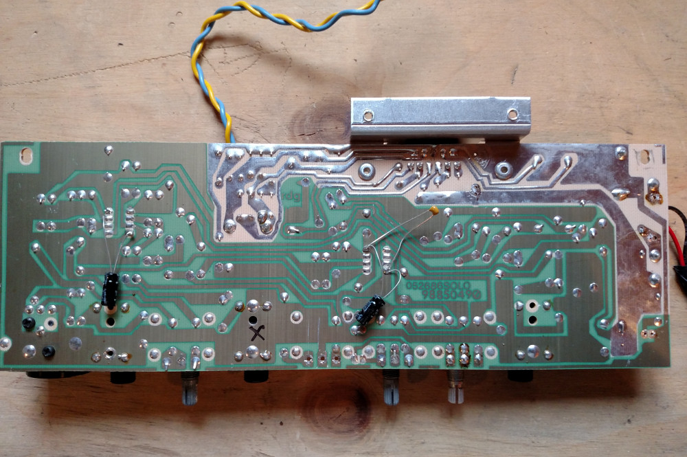
The first thing that I thought about trying was to take an old boombox or AM/FM radio, and hacking in an off-the-shelf bluetooth audio adapter either into an available AUX input channel, or somehow hijacking another available audio channel (like the one used for the tape input). After a few tries scrounging around, I wasn’t able to find a boombox or radio that met all of my needs. Either they were too complicated internally (they didn’t have easily accessible audio channel lines for AUX, or tape), or they just didn’t have the right form factor. But eventually, after a bit of digging, what I did find, was a 10-15 watt Peavey Solo guitar & microphone amplifier. Alright!
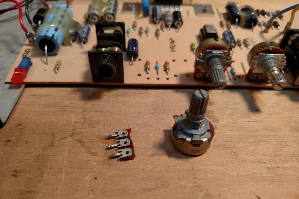
It had a broken potentiometer for the aux volume control that was rattling around inside of the enclosure. But that’d be an easy fix with a through-hole 50K pot soldered back on to the main board, and off to the races we go!
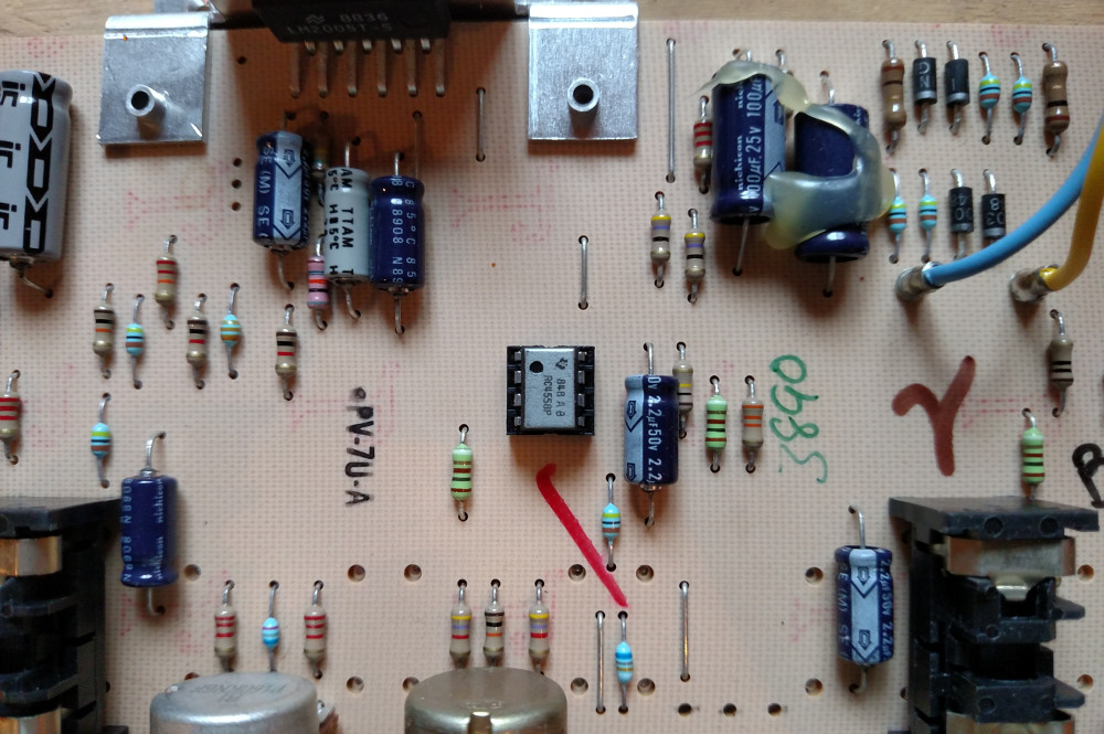
Unfortunately, after plugging it in, and listening to the audio quality, the mood got a little deflated. Although it was loud, with 15 watts, and a 4Ω woofer, the fidelity was pretty poor, and I think that it was on account of the amplifier’s board layout, cost-reducing efforts, and by driving the power amplifiers beyond their specifications (producing clipping). The amplifier also had a pretty solid 60hz buzz, which at the time, I didn’t really know how to solve. Turns out, appropriate grounding and employment of bypass capacitors (to reduce noise on the power rails) are incredibly important to producing a clean amplified audio signal.
I had a second problem too. I wanted to have the bluetooth adapter’s power supplied by the amplifier board. After hacking the two together to test things out, I could hear really awful RF interference emitting from the amplifier. The reason for this had to do with the grounding technique of the amplifiers board layout. It definitely wasn’t in a star pattern, and it looked like power and signal grounds were intermixed, which I guess can lead to problems. The amplifier chips on the board also lacked proper bypassing, presumably to reduce the COGS and manufacturing costs of the product.
I played around with adding some bypassing to the amplifier chips, but ultimately, trying to fix the problems started to seem less and less feasible for me to do in a reasonable amount of time.
Well, that didn’t work. So, short story long, let’s roll our own!
Disclaimer: There are many good quality bare-bones amplifier boards that are available pre-assembled, for a very low price. Just checkout parts-express. Some even have integrated bluetooth modules. But if you want a learning experience, and a special feeling of satisfaction for a job well done, then why not try doing it yourself!
New goals
Going back to the drawing board a little bit, I picked these as my new goals:
- Build a self-contained mono amplifier/speaker system that will fit into the old Peavey guitar amp enclosure.
- A circuit that’s easy enough for me to understand.
- An off the shelf bluetooth adapter that can be integrated into the circuit.
- Provides 10-20 watts through a 4Ω load (so that I can re-use the speaker)
- A simple, yet snazzy chassis and face plate that fits into the cavity left by the stock Peavey chassis, and one which provides heat sinking for the amplifier chip.
- An integrated 120V AC power supply.
Bluetooth
This off-the-shelf bluetooth adapter is from XINGDONGCHI, and is great for this project for three reasons:

- It’s cheap (< $9 shipped).
- The presence of the USB port means that it’s powered by 5v.
- The presence of a 3.5mm headphone jack means that the audio is easy to intercept.
This device isn’t actually a USB audio adapter. It provides audio through a 3.5mm headphone jack, and only uses the USB connector for 5v power. It’s pretty ideal for integrating into an amplifier project.
To prepare the adapter for integration, first remove the plastic enclosure by placing it in a vice, along its seam, and gently applying compression until the two halves pop apart. Bingo. Then, to provide a more permanent integration point, depopulate the USB male connector, and solder on a 4x1 male pin header. That will provide power and grounds to the two outer pins, leaving the two inner pins unused.
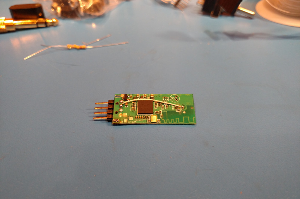
This particular adapter has an indicator LED, which blinks at different patterns according to whether or not something is paired to it. I chose to depopulate the LED as well, and run its signal (which is connected directly to the SoC via a 1K resistor), out to one of the unused pins of the male pin header. My goal for that is to incorporate the blinking pattern into the front panel of the amplifier somehow.
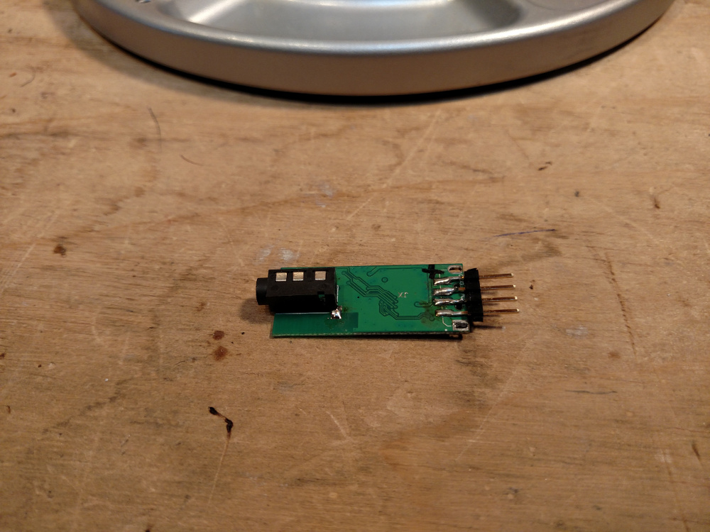
Now, since this project is going to be a mono amplifier (there’s only one speaker), you might think that you could forgo the 3.5mm audio jack and somehow route a mono signal through the second unused pin of the male header. But that would mean that the signal and the power source for the board would directly share a common ground pin. That may work, but to do our due “grounding” diligence, I decided to keep the 3.5mm jack, so that we would have separate grounds for the signal, and for the power source of the adapter.
Get down to business
Okay, so building an amplifier… The great thing is that there is no shortage of in-depth, detailed information out there on how to build DIY audio equipment. Unsurprisingly, that also turns out to be a downside as well, as it can be a bit overwhelming to wade through it all. Thankfully, there’s is a great article in MAKE that details pretty much exactly what I want to do:
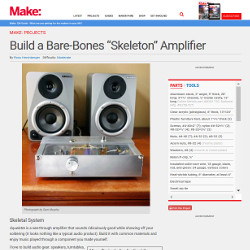
They call it the “Skeleton amplifier”, and it’s based on the LM1875 chip, which has gained popularity for its ease of use, its quality, and power. The project also provides a circuit diagram for a power supply, and parts list, configuring two LM1875s as an 11 watt per channel stereo amplifier. Best of all, I only have to build 1/2 of the amplifier circuit, since I only need mono! Yes!
Parts
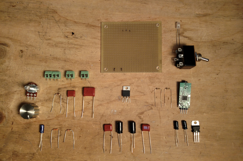
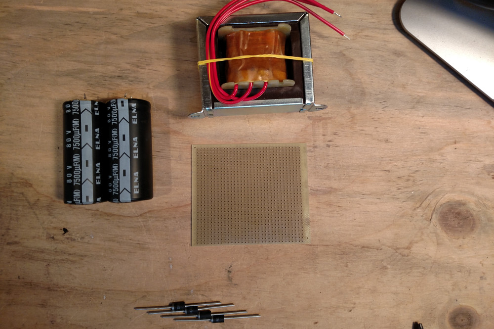
Here’s the parts list for the mono amplifier. These are mostly taken from the Skeleton Amplifier guide, and I was able to source almost everything from Mouser (as opposed to radioshack) reducing the cost somewhat. I include a couple additional components for the purpose of integrating the bluetooth adapter. I was able to salvage capacitors and other various things from other derelict amplifiers that I happened to have in the junk pile. In particular, from a fancy, yet busted Kenwood amplifier, I pulled two enormous 7500μF 80V caps that I then used for the power supply, and a large aluminum heatsink which I used to dissipate the heat form the LM1875. Below, I list the part numbers, where available, but feel free to find any part that meets or exceeds the specs described below.
If you don’t have a ready supply of capacitors and resistors, getting a pre-assembled kit from ebay or amazon that contains a wide variety of electrolytic, ceramic, and film capacitors is a great way to go. Resistor kits are also available, and relatively inexpensive. If you do buy capacitors or resistors from mouser, and you can spare a few extra dollars, buy more than you need, in quantities of 10 to reduce the per-unit cost. Having them around is really handy.
Note: the parts list below is for a MONO amplifier
Capacitors
- 2x - 4700μF to 7500μF (35-80V) electrolytic capacitors (ECA-1EHG472)
- 2x - 100μF 25V electrolytic capacitors
- 1x - 22μF 25V electrolytic capacitor (ECE-A1EN220X)
- 2x - 1μF 25V film capacitor (ECQ-E2105KF)
- 3x - 0.1μF 25V film capacitors (ECQ-E4104KF)
- 1x - 0.22μF 25V film capacitor (ECQ-E2224KF)
- 1x - 0.33μF 25V film capacitor
Resistors
- 1x - 1Ω 1W metal film resistor (CPF11R0000FKEE6)
- 1x - 100KΩ linear taper, through-hole potentiometer, 16mm shaft, don’t skimp, and get a nice one (P160KNP-0QC15B100K)
- 2x - 10KΩ any type resistors
- 2x - 22KΩ any type resistors
- 1x - 220KΩ any type resistor
- 1x - 1KΩ any type resistor
Power
- 1x - 25.2V out (115V in) power transformer (Triad F-41X)
- 4x - 40-60V 5A Schottkey Diodes (SB560-E3/54, 1N5822)
- 1x - 120V rated SPDT panel mount toggle switch
- 1x - 500mA 250V time lag fuse cartridge (0218.500MXP)
- 1x - Inline fuse holder (go to Radioshack and see what they have that will fit a 5mmx20mm fuse)
- 1x - 2-prong power cable
IC
- 1x - LM1875T
- 1x - XINGDONGCHI USB Bluetooth audio adapter (or something that seems like it’d be easy to work with)
- 1x - 2N706 NPN Transistor
- 1x - 5V voltage regulator (L7805CV)
Other
- 2x - Perf boards
- 1x - 1x40 breakaway male pin header
- 1x - A stylish knob for the volume potentiometer
- 1x - LED (I chose a neat defuse white)
- 6x - 2 pole 5mm pitch screw down terminal blocks (optional, but nice. Note: only 4 ended up in the picture below)
Chassis and heat dissipation
- 1x - 4x2x0.125” x 10 7/8” (or whatever dimensions you need) architectural aluminum stock.
- 1x - Aluminum heatsink (optional, you can alternatively find a way to thermally bond the amplifier chip to an aluminum chassis)
- 1x (at least) - TO-220 thermal insulator, to electrically insulate the LM1875, but still allow it to thermally bond to the heat sink (43-77-20G)
- 1x - Silicone heat sink compound
Mounting hardware
- 1x - Nylon 1/4” P-Clip (For tension relief of the power cable)
- 5x - #6 nylon screws
- 5x - #6 nylon nuts
- 5x - #6 nylon washers
- 8x - #6 1/4” nylon spacers
- 4x - #6 1/2” long pan head metal screws
- 2x - Small metal screws (secure the power supply)
- 2x - Small metal washers (secure the power supply)
- ?x - Small screws to secure the heat sink
Power Supply
Be very careful with main power!
Also be careful with these large capacitors. They maintain high voltage even after they are disconnected from power. Properly discharge capacitors before handling the power supply circuit again.
This part is actually really satisfying. We get to make a bi-polar 20V DC power supply that can be integrated into the guitar amp enclosure. It’s actually surprisingly simple, and interesting.
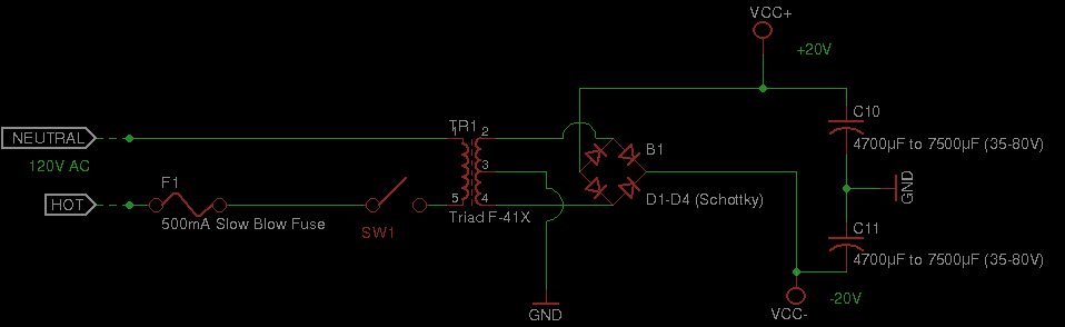
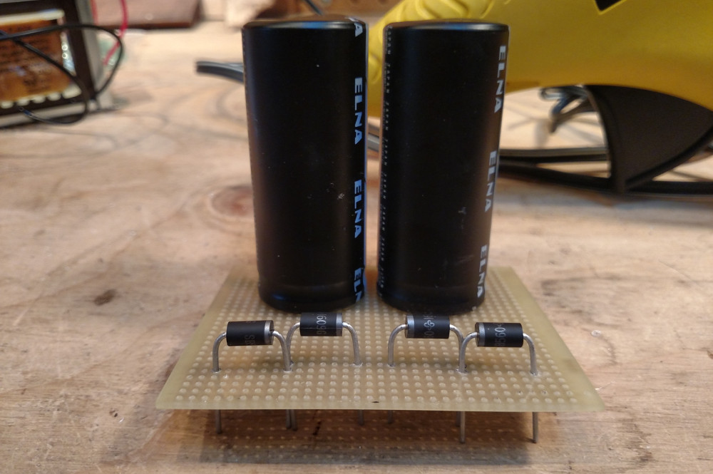
So, the basic idea is that the transformer steps down the AC voltage to around what we’re after: 25V, and the arrangement of rectifier diodes (in a bridge circuit configuration) serve to efficiently convert alternating current into a positive 25V and a negative 25V DC output. The center tap of the transformer serves as our ground reference.
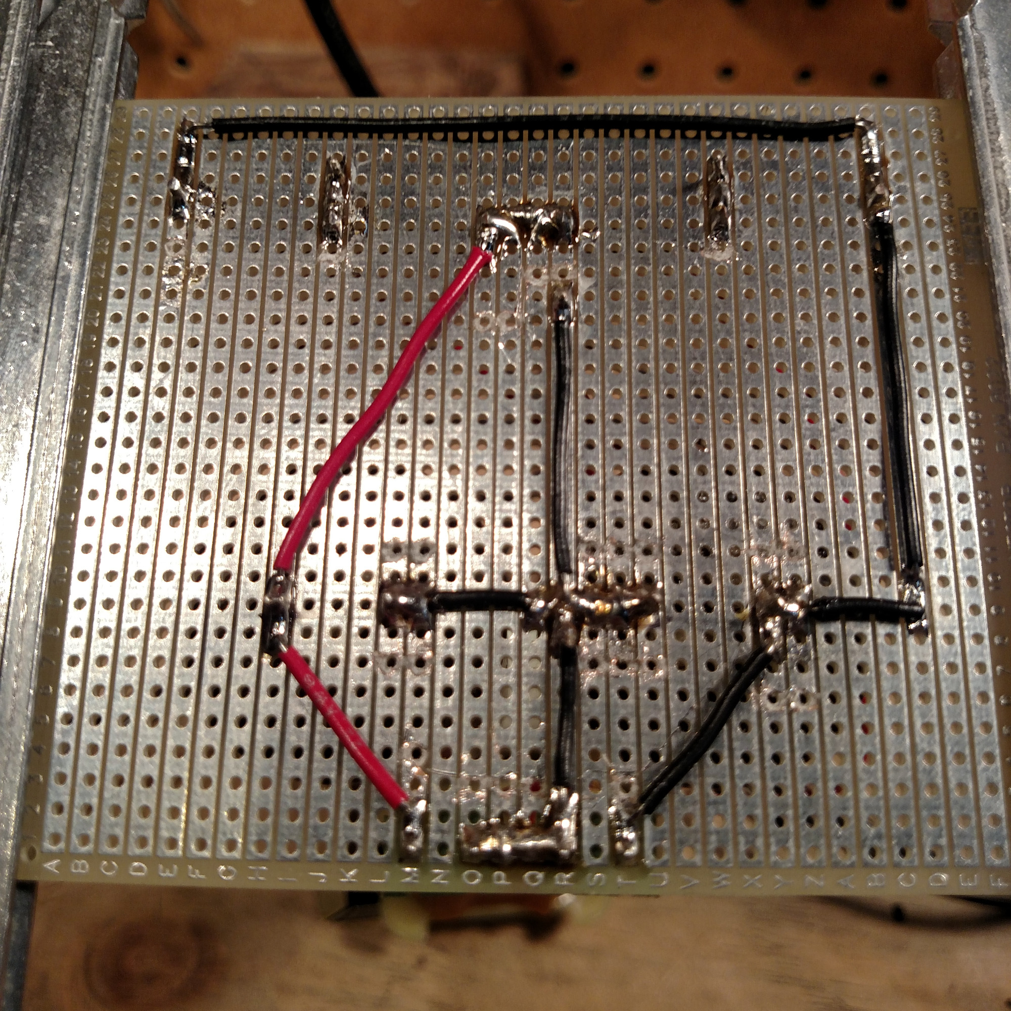
To get the diodes and capacitors to fit into a through-hole perf board, you may need to drill out the holes with a 5/64” or 3/32” bit. Below is my attempt at a power supply board using a strip contact board, where there are conductive traces along the horizontal axis of the board. I actually don’t rely on these traces exclusively for the power supply, and instead add jumper wires to better handle the current and voltage requirements. Maybe overkill, but better safe than sorry. To secure the capacitors, deposit hot glue on the bottom of them prior to placing them on the board.
By the way, if you do use perf boards with strips of contacts, you can use an x-acto knife, a drill bit, or a special tool to disrupt the traces where necessary.
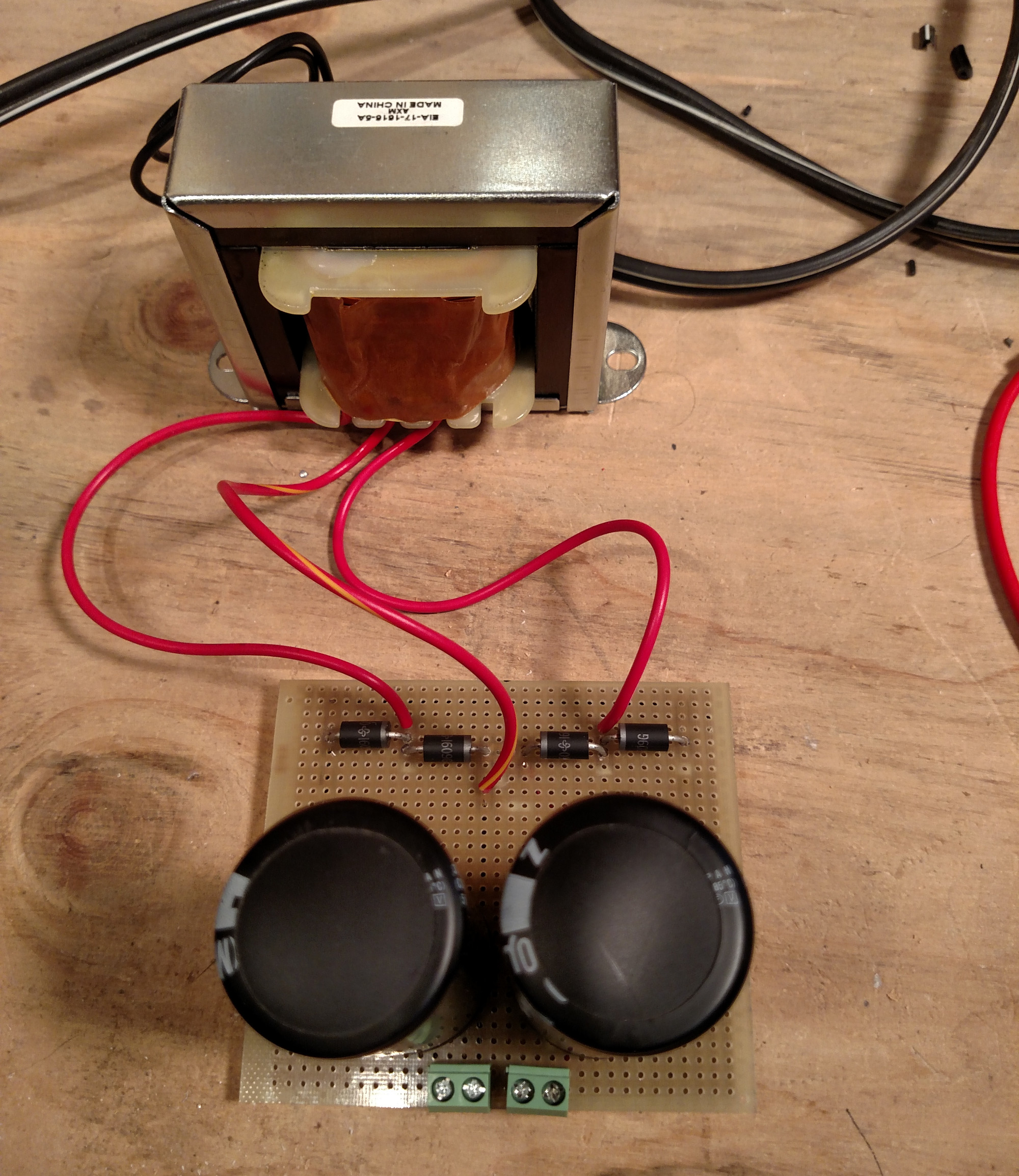
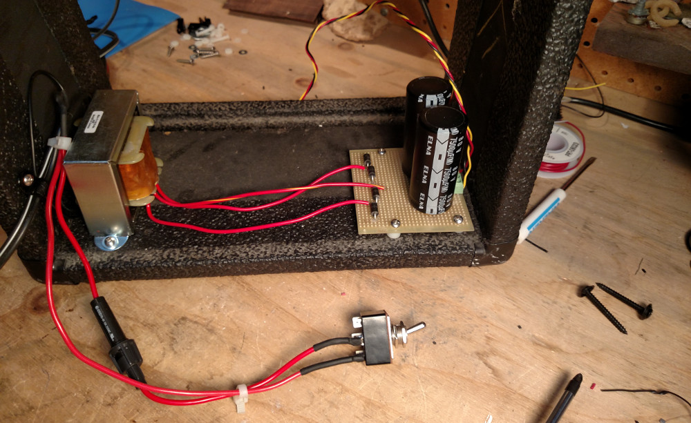
Once everything is laid out and soldered together, attach the transformer. The lead with the stripe is the center tap, and is attached to the ground plane of the board.
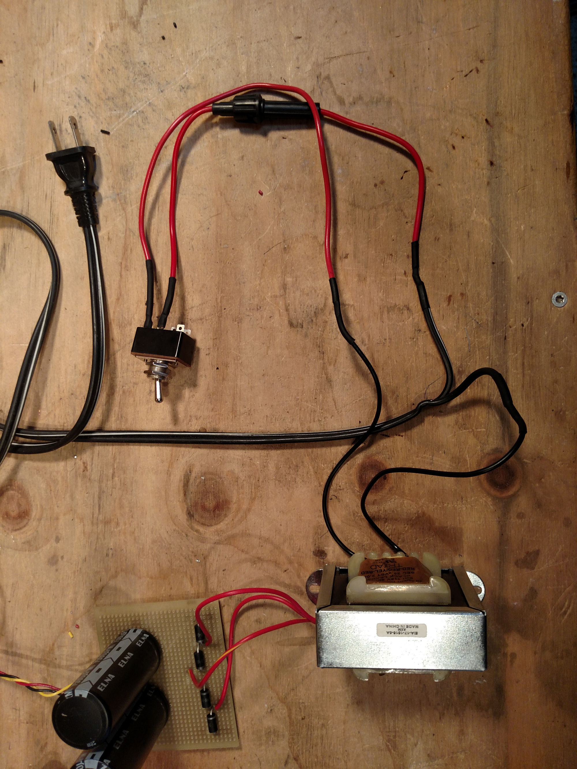
Next, splice an old 2-prong power cable and solder the fuse holder to the hot lead (the one with the white stripe). Then, solder the fuse holder to your power toggle switch. Since this is carrying main power, be sure to choose a toggle switch that is rated for 120V. Solder a lead from the opposite pole of the toggle switch to one of the black input leads of the transformer, and then finally solder the neutral lead of the power cable to the other black input lead of the transformer. Here, I use black heat shrink tube around all of the solder joints to insulate them. Now, just plug it in, and test the voltage. From the 25V AC transformer, you will likely see somewhere in the neighborhood of +/- 20V. The drop in voltage is due to the accumulated forward voltage drop of the diode rectifier bridge. Be very careful, even after the power supply has been disconnected from main power, the capacitors will hold a voltage for quite a long time. If there is no load connected to the power supply, carefully, without actually touching any conductive surface, take a 1k resistor and short the poles of both of the capacitors. I taped a resistor to a stick, and used that to discharge each capacitor. You can use a screw driver with an insulated handle to short the poles, but this will most certainly cause arcing.
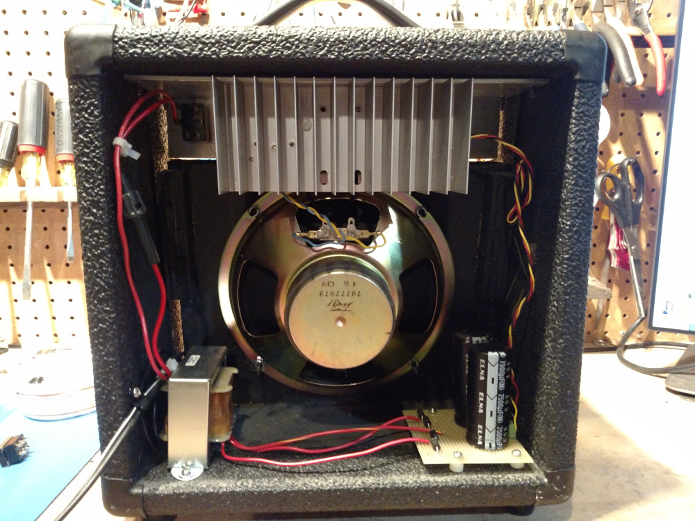
This is how it ended up looking once installed in the enclosure. I drilled holes through the PCB and used #6 metal screws, and #6 nylon washers and #6 1/4” nylon spacers to raise the PCB off of the bottom of the enclosure. The transformer is held down by small metal screws and washers. To relieve tension on the power cable, it is attached to the side of the enclosure by a black 1/4” P-Clip.
Amplifier
The amplifier circuit itself is essentially identical to the LM1875 amplifier circuit detailed in the “Skeleton” Amplifier project. In that project, you of course build a pair of amplifiers, for stereo. Here we only need one. There are only a few main differences between the Skeleton circuit, and the one below.
- It takes stereo audio input, and sums the left and right signal into a single mono source.
- There is no external audio input source. The audio signal from the Xingdongchi bluetooth module is the only source.
- There is an additional +5V power regulator circuit that is used to supply power to the bluetooth module.
- There is a transistor that is used to control an external indicator LED.
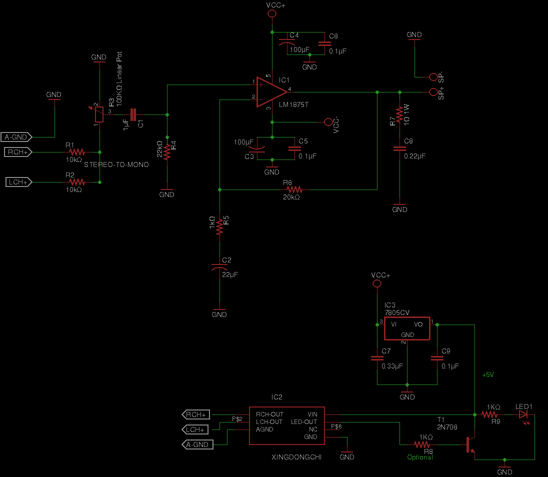
I want a single LED power/connectivity indicator for the front panel, but the LED indicator of the bluetooth module doesn’t quite behave in a way that I need. For instance, it doesn’t illuminate until the SoC boots (which takes a second or two). Secondly, I want to keep the design open for adding an AUX channel port, and allow for the bluetooth module to be powered down while the AUX channel is being used. This means that I cannot rely solely on the output of the bluetooth module’s LED output. To solve this, I use an NPN transistor, and create a not gate, which essentially inverts the LED indicator signal that comes from the bluetooth module. The result is that the LED is on by default, and blinks inversely to the signal of the bluetooth module’s LED output.
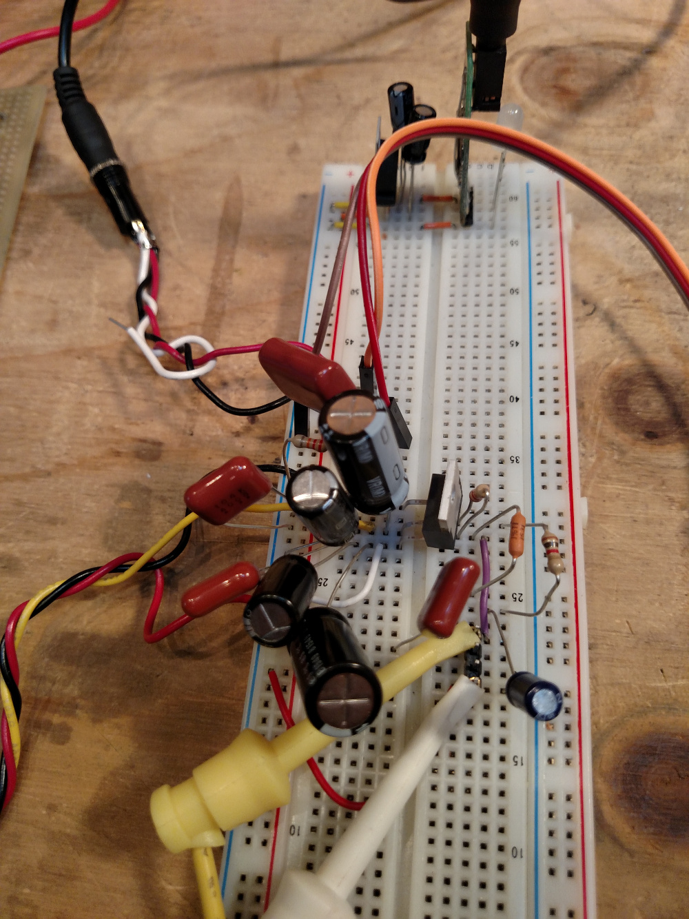
Before trying to come up with a board layout, I tried the circuit out on a breadboard, to see how it worked. This doesn’t actually give you a sense of how the amplifier will sound when laid out on an actual board. The contacts between components are not terribly secure, there are a lot of long leads that can pick up interference, and the grounding typically won’t be very good, causing ground loops, which can again, introduce interference. In particular, I noticed that the bluetooth module introduced quite a bit of interference, even though the amplifier is pretty well protected by bypass capacitors. Also, it is not a good idea to run the amplifier for very long without some kind of heat sinking. It gets extremely hot, even after a few seconds of activity. Still, this felt like an important step.
Layout, in Theory
Probably the trickiest part of this project is coming up with a sensible layout. There are two main things to focus on.
Bypassing
Bypass (or “decoupling”) capacitors5,6 connect from the power rail to ground and serve to dampen noise in the form of voltage fluctuations on the power inputs to our ICs. It’s important to place these capacitors as physically close to their IC as you can. Traces inevitably have some amount of impedance, so the longer the trace, the more likely it is to pick up noise.
Grounding
A “star” grounding configuration7,8 is pretty important for this amplifier. This basically means that all ground junctions should run directly to a single point, and then that point becomes the common ground to the chassis. This prevents interactions between circuit features that could cause noise and instability.
Layout, in Reality
You may not end up getting a perfect star ground configuration, but give it a shot. I wasn’t entirely successful in getting a perfect star ground configuration, but it’s not bad for a first attempt.
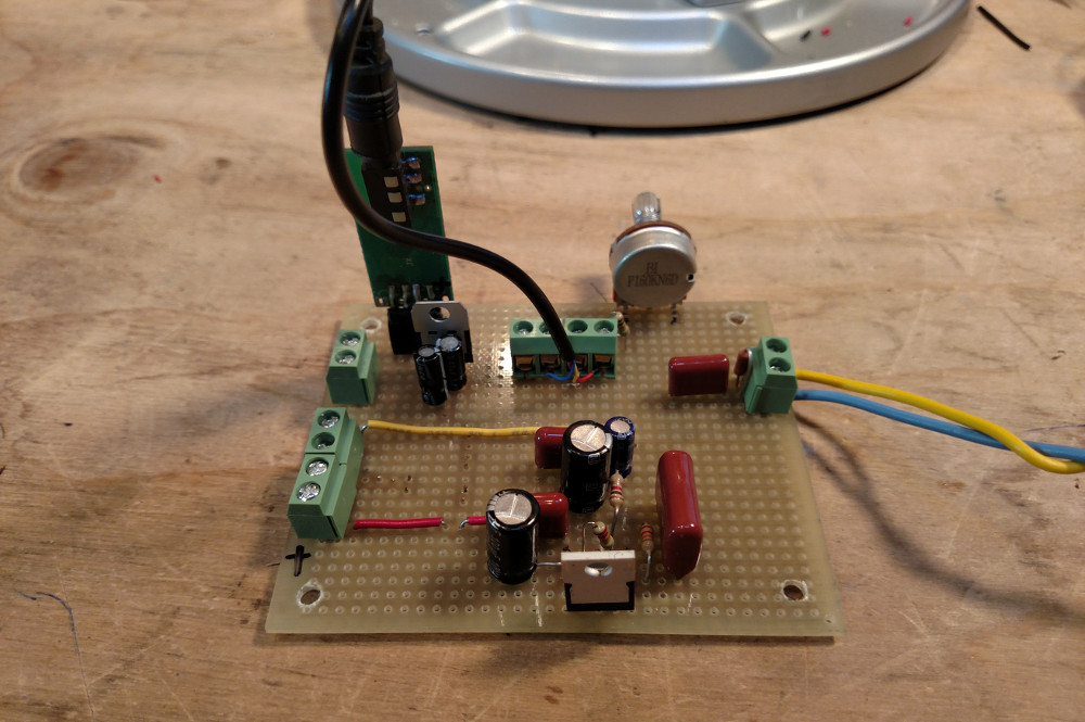
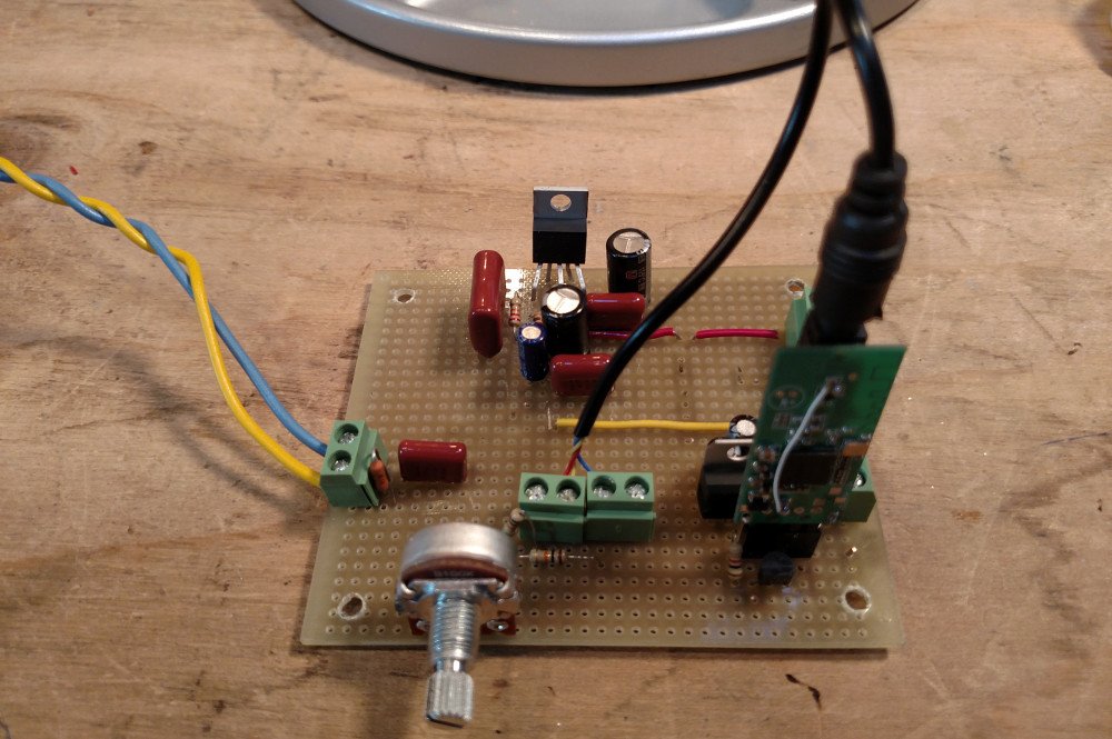
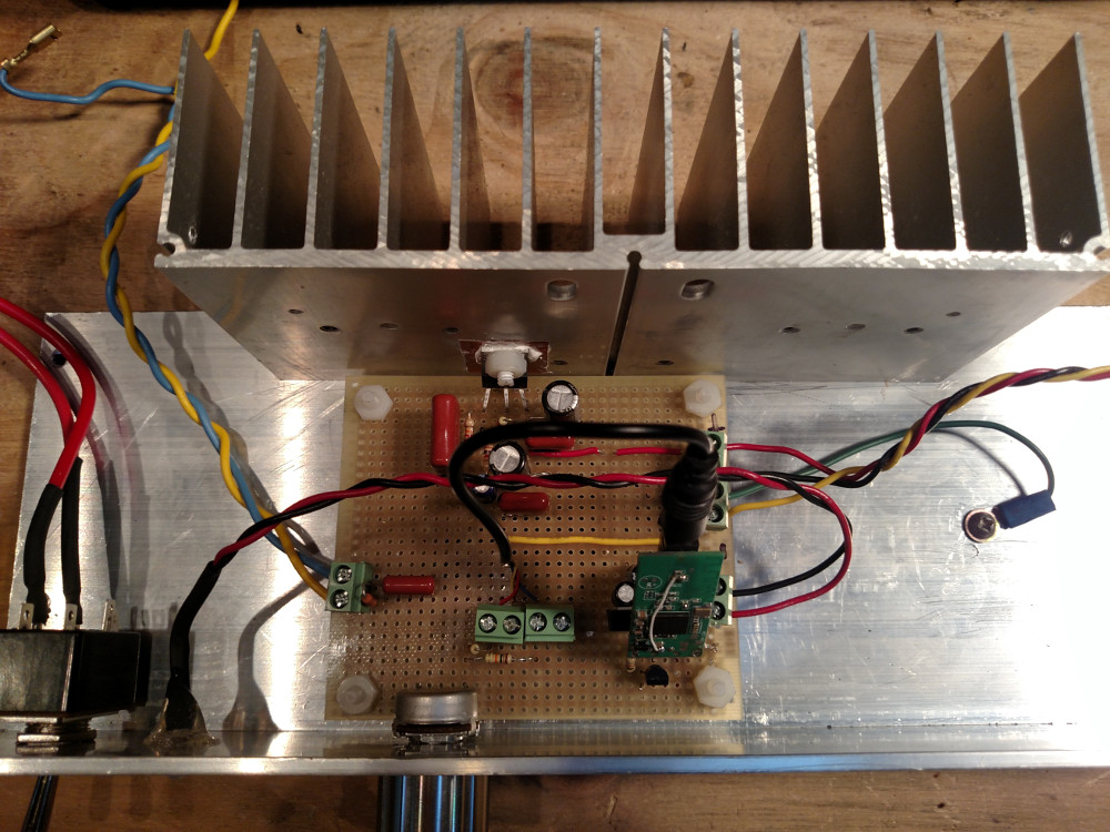
I used screw down terminals to connect all of the external parts. In Fig 1, starting from the top left, the screw down terminal closest to the bluetooth module is for the indicator LED, that will be attached to the chassis. The one below it is for the power. I only had 2-pole terminals available, so I had to use two of them for the power supply attachment point. These are wired as VCC- on the top, two grounds in the middle, and VCC+ at the bottom. The second GND terminal block will be used to ground the chassis using a lead with a spade connector. For the audio input, there are a total of 4 poles. Each channel has an independent ground, of which, I only use one. The terminal to the right is the output to the speaker.
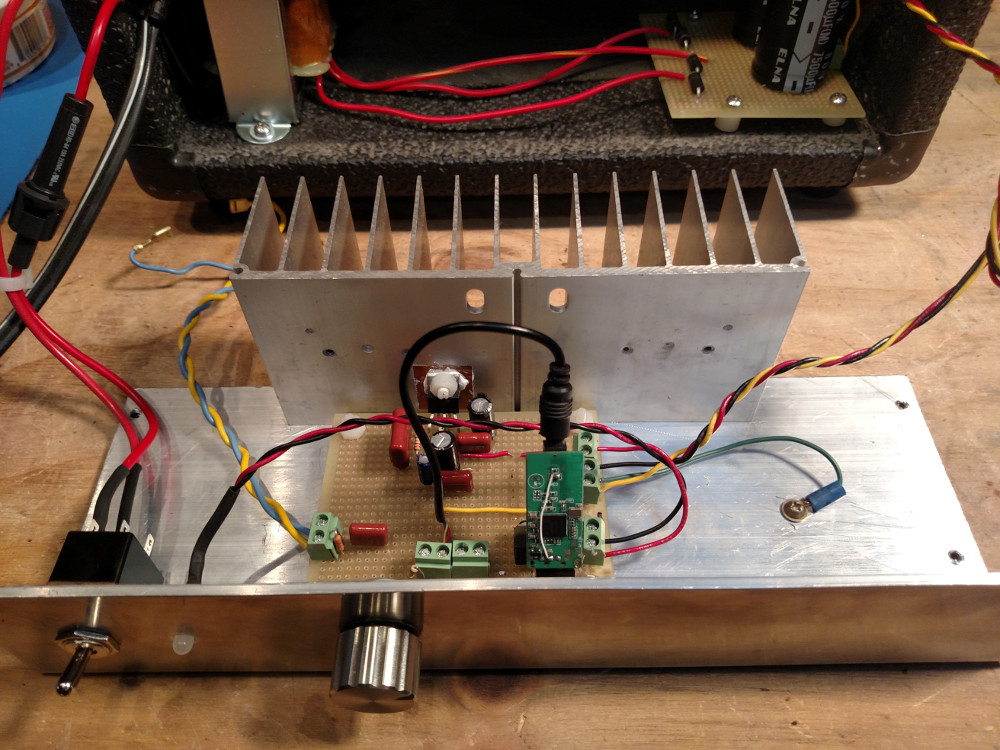
The volume potentiometer is positioned flush with the front of the board so that it can be attached to the chassis’ front panel, and the LM1875 is positioned flush with the back of the board so that it can be bonded to the heat sink. I did not bother screwing down or heat sinking the L7805CV voltage regulator, since it is not going to get terribly warm, nor do I intend to move the finished amplifier around very often.
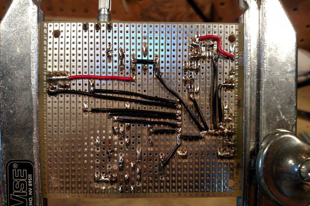
Here is the layout of the underside of the board. In order to reduce the overall inductive surface area of the circuit, I was diligent about disrupting the on board traces, so that they were as short as possible. Again, you can use an x-acto knife, a drill bit, or a special tool for this.
Chassis and Front Panel
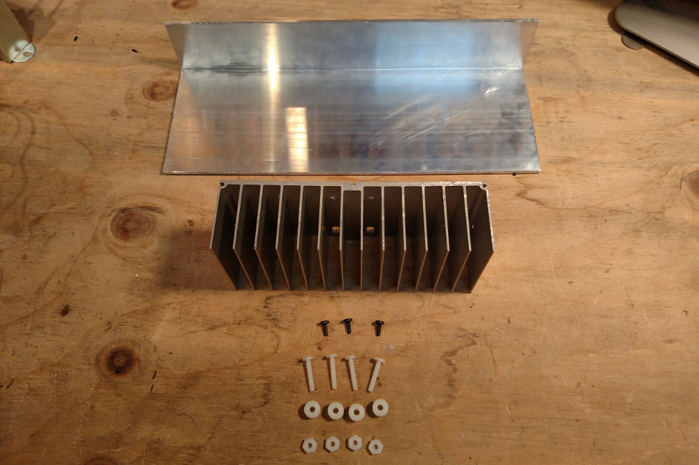
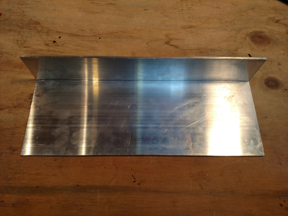
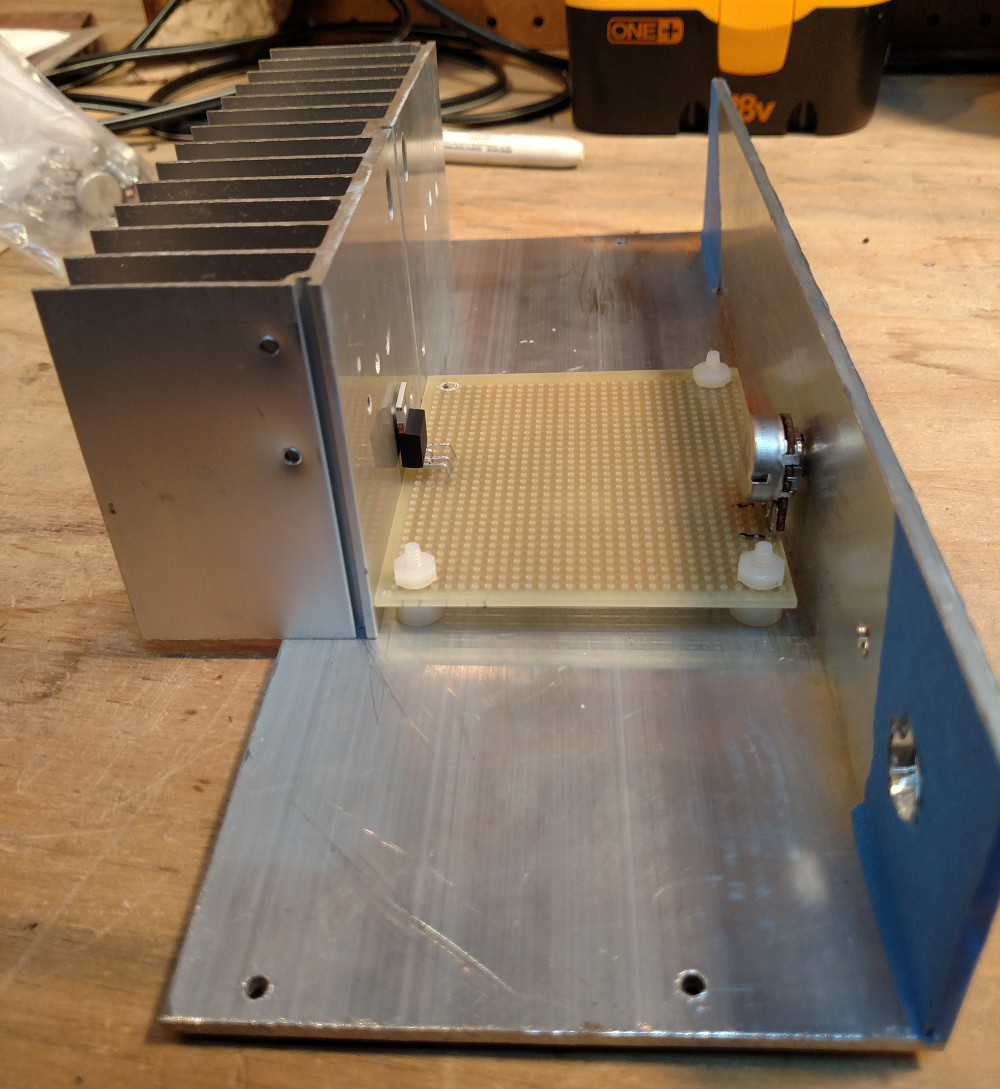
A single piece of 4x2x0.125” x 10 7/8” angle architectural aluminum serves as both the chassis and the front panel of the amplifier. I was able to source this from a local metal supply shop that sold 4x2x0.125” angle architectural aluminum by the inch. “Architectural” in this context means that it has a crisp right angle on the interior, which is perfect for this application. The heat sink and circuit board are both mounted to the 4” wide section of the angle aluminum, and the 2” section serves as the front panel. Because there is an inside angle of 90°, the circuit board can fit up flush against the front panel.
To help make clean holes, and to more easily lay things out, put down a layer of masking tape over the outside surface, and drill inward. The front panel will have a power switch, a volume knob, and an power/bluetooth connectivity indicator LED.
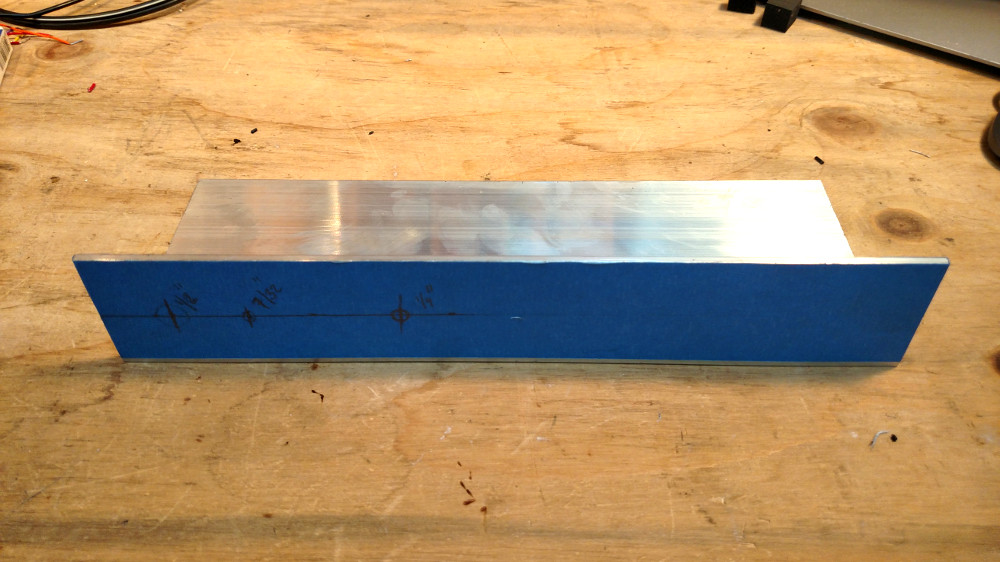
If you don’t have a drill press, use a center punch, a nail, or screw to make a centered guide for the drill bit.
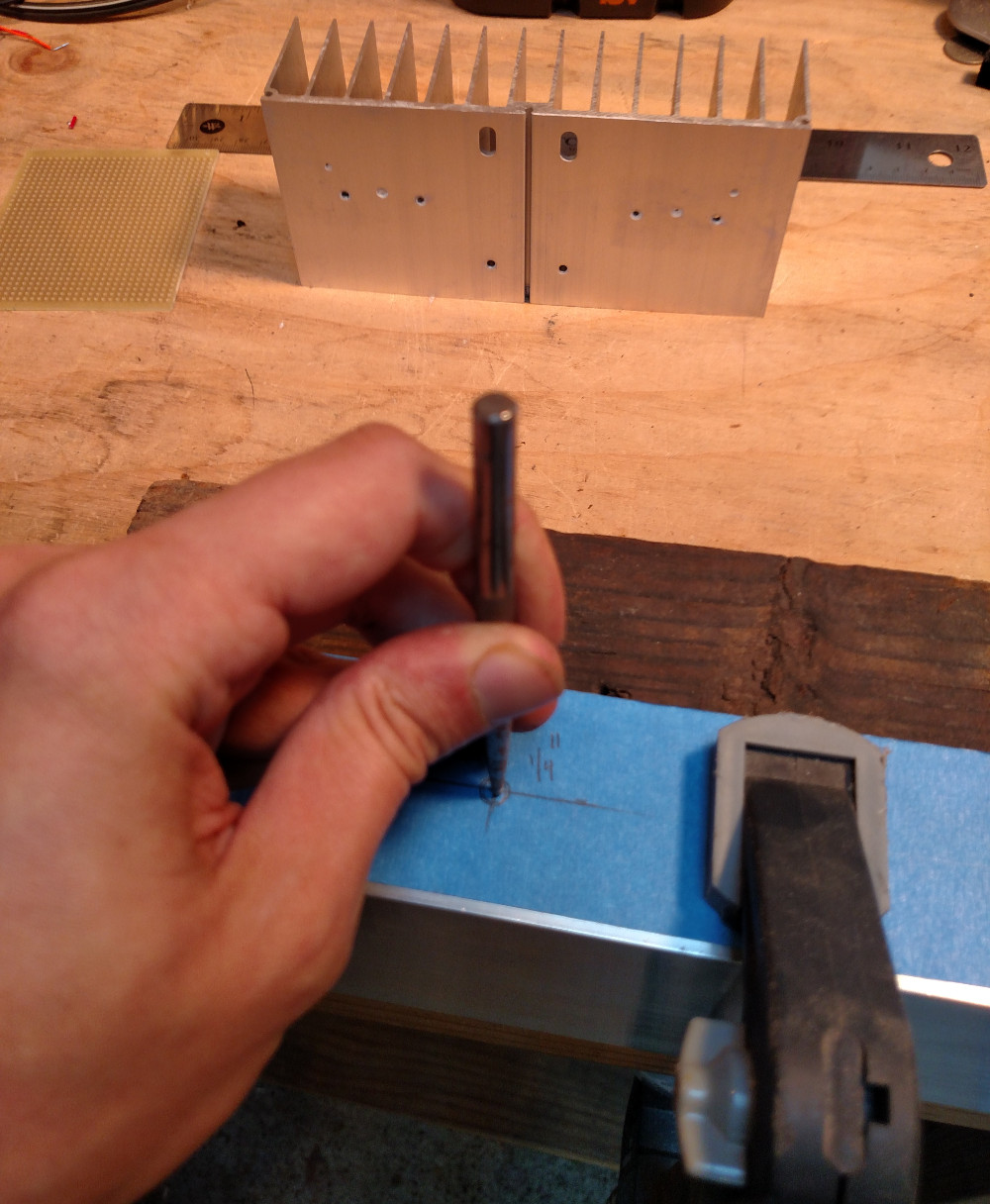
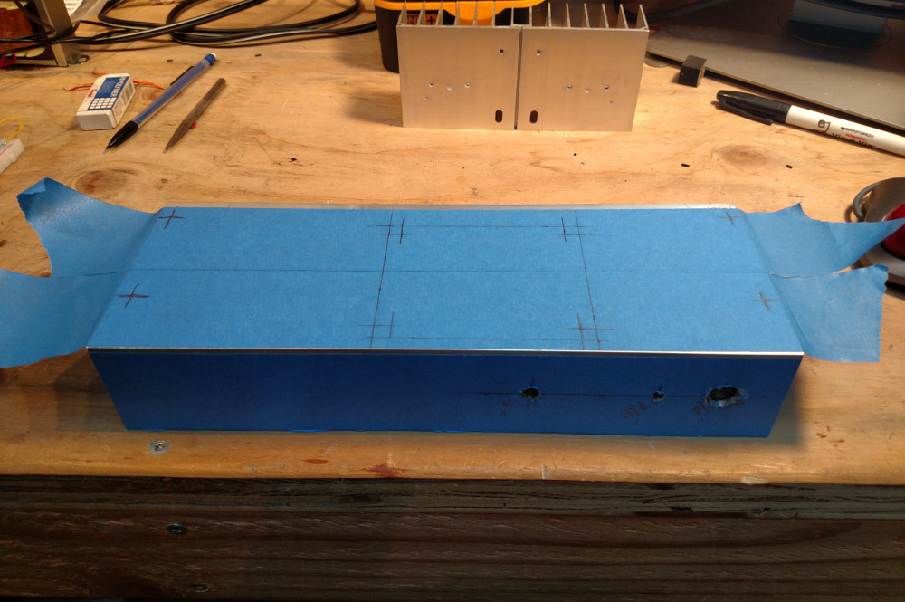
To get the spacing correct, you can always try playing around with the boards orientation, and layout of externally accessible components, so that you can make sure that the heat sink, the amplifier, the holes in the chassis, and the volume potentiometer all align.
The heat sink I use has gaps in three locations across its length, and are easily tapped with a small screw. Once everything is in place, mark the location of the holes for the heat sink with a sharp nail.
Once you’ve drilled the holes, knock down any burs with a metal file, and affix the heat sink. To attach it to the chassis, just screw it to the bottom.
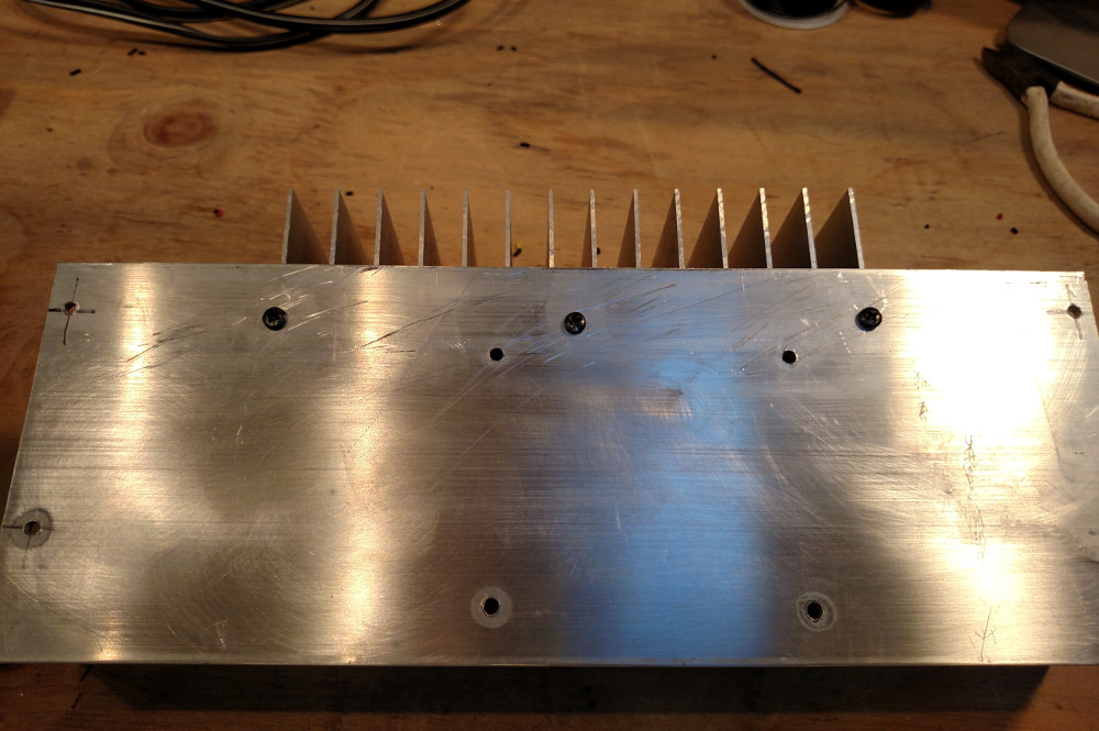
To give the aluminum a nice finish, use a high-grit sand paper (i.e. 600 grit) to remove any swirls, and to produce a slightly matted grain finish by sanding in a constant horizontal direction.
Assembly
All that’s left now, is to bolt it all together. To mount the amplifier circuit, use #6 nylon screws, nuts, and 1/4” spacers. To bond the LM1875 to the heat sink, use a TO-220 thermal insulator, along with some silicone thermal compound (on both sides of the thermal insulator), securing it with another #6 nylon screw, washer, and nut. It’s important for the LM1875 to be electrically insulated from the heat sink, but thermally bonded.
Ground the chassis using a crimped spade connector, and attach the other end of the lead to the star ground of the amplifier circuit. I used the spare GND terminal block for this.
Finally, secure the power switch, the external LED, and the volume knob. Not pictured here, but I encase the bluetooth module in heat-shrink tubing to better protect it from an accidental short.
Results
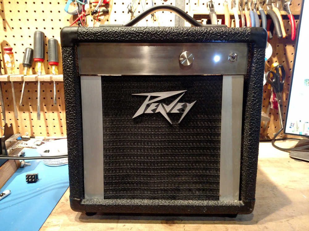
In the end, things turned out pretty well. The amplifier sounds great, and is definitely loud enough for my small space. I also like the clean look of the aluminum face plate, and defuse white LED. I am especially happy about the volume knob. I found it quite a while ago in a stall at an electronics MEGA store in Akihabara, Tokyo, and have been holding on to it ever since; sometimes even daydreaming about what it might one day be used for.
It isn’t perfect. There is a bit of audible interference from the bluetooth module, but it is only detectable at high volume, and without the audio source playing. I also can hear a bit of DC feedback when the LED blinks, which I think is due, again, to improper grounding. Even so, it still sounds great to me!
Next Steps
I suspect that the sound quality of this amplifier can be improved. The enclosure has an open back, and uses a 4Ω woofer driver, which doesn’t seems to have a very wide range. It has decent bass, but muffled mids and highs. The next step for this project will be to hack the enclosure, sealing the back and air gaps, and opening up a bass reflex port so that the bass can resonate more efficiently. A full range speaker driver would also be a nice addition. These drivers often have two integrated speaker cones (a tweeter and a woofer) and built-in cross-over circuitry. In the mean time the lab is filled with pleasant tunes once again, and I had a great learning experience.
References
- Power Supply Schematic - /images/posts/amp/Power-schematic.png
- Amplifier Schematic - /images/posts/amp/Amp-schematic.png
- Bare-Bones ‘Skeleton’ Amplifier - http://makezine.com/projects/build-bare-bones-skeleton-amplifier/
- Bridge Amplifier Circuit - https://en.wikipedia.org/wiki/Bridged_and_paralleled_amplifiers#Bridged_amplifier
- Demonstrating the Effect of Decoupling Capacitors - https://www.youtube.com/watch?v=UW_XFGGTh0I
- EEVblog #859 - Bypass Capacitor Tutorial - https://www.youtube.com/watch?v=BcJ6UdDx1vg
- Star Grounding in Tube Amplifiers - http://www.geofex.com/article_folders/stargnd/stargnd.htm
- Solving Ground Loop Problems - Star Grounding - http://www.lh-electric.net/tutorials/gnd_loop.html
- Grounding and Shielding for your DIY Audio Projects - http://diyaudioprojects.com/Technical/Grounding-Shielding/
Comments